Design of Gate and Runner Arrangement of Plastic Injection Molds
Lyter Engineering Design of Gate and Runner Arrangement of Plastic Injection Molds
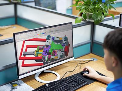
We strive to optimize the injection mold design. It mainly refers to the optimization of the design of the gating system and the cooling system. The selection of the gate form and location is very important. The following we will discuss the gating system research and design.

How plastic fills the cavity
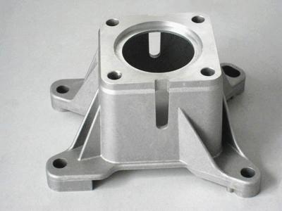
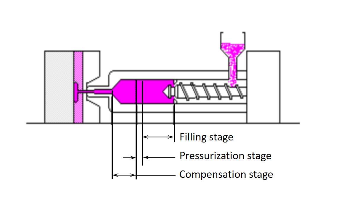
The process of plastic injection into cavity molding products can be divided into three stages: filling, pressurization and compensation
How plastic fills the cavity
Filling stage:
During the filling stage, the plastic is squeezed into the cavity by the screw of the injection machine until it is just filled. When the plastic enters the mold cavity, the plastic will solidify very quickly when it contacts the mold wall, which will form a solidified layer between the mold wall and the molten plastic.
Pressurization stage:
Although all the flow paths have been filled in the filling stage, there are still gaps in the edges and corners. In order to completely fill the cavity, it is necessary to increase the pressure at this stage to squeeze additional plastic into the cavity.
Compensation stage:
When plastic is cold solidified from a molten state to a solid, there will be a high shrinkage rate of about 25%, so more plastic must be injected into the mold cavity to compensate for the shrinkage caused by cooling.

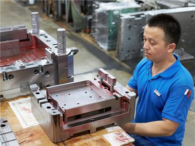
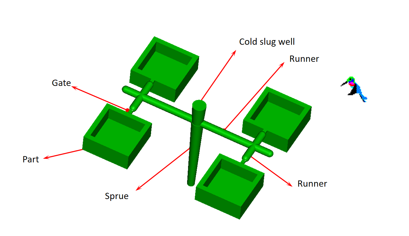 The sprue design
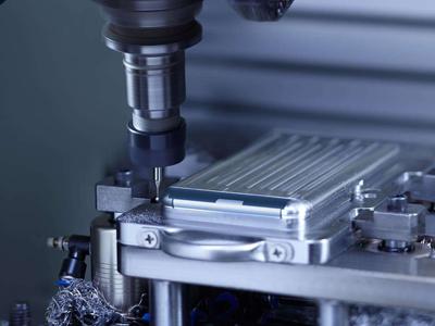
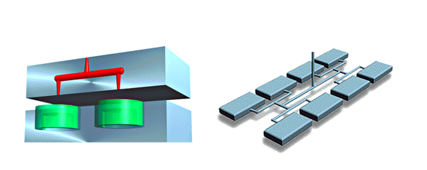
 The runner design
Circular section
Advantages: The ratio of surface area to volume is the smallest, and the loss of pressure and temperature is small, which is conducive to the flow and pressure transfer of plastics. The runner has the highest efficiency and economy.
Disadvantages: It must be divided into half on the cavity and core mold inserts, which brings certain difficulties to the mold processing and high cost
“U" shaped section
Advantages: Its section form is close to a circular section, and it only needs to be machined on one side of the mold.
Disadvantages: Larger heat loss compared to circular cross-section, more runner waste.
Trapezoidal Section
Advantages: Only one side of the mold needs to be machined, which is convenient for processing and tool selection.
Disadvantage: large heat loss.
Square section
Advantages: The runner efficiency is high, and it only needs to be processed on one side of the mold, which is convenient for processing and tool selection.
Disadvantages: The flow resistance is large, and the ejection force is large. So it is less used.
Semicircular section
Advantages: Good mold release, suitable for molds with complex parting surfaces. Just work on one side of the mold.
Disadvantages: high flow resistance, greatly affected by condensation, lowest flow channel efficiency. So it is also less used.

Calculation of runner cross section

Factors to consider when sizing a runner
-The volume and wall thickness of the part.
-The distance from the sprue to the gate.
-The cooling method of the runner.
-The fluidity of the molding resin.
- It is convenient to use automatic gate cutting device.
-The cross-sectional thickness of the runner is greater than the wall thickness of the product.
-The length of the shunt channel should be as short as possible, and when it cannot be short, its section size should be increased accordingly.
-For resins with poor fluidity such as glass fibers, the cross section of the runner should be larger.
-At the corner where the direction of the runner changes, the cold slug well should be set appropriately.

Kategorien
neuestes Blog
 Building A, Dingfeng High-tech Park, Shapuwei Community, Song Gang Street, Shenzhen, China, 518105
NO.1 Jinchang Road, Henan Industrial Zone, Chang’an Town, Dongguan City, China


Bei Anfragen zu unseren Produkten oder Preislisten wenden Sie sich bitte an uns und wir werden uns innerhalb von 24 Stunden bei Ihnen melden.
© Urheberrechte ©: 2026 Lyter Engineering Ltd. Alle Rechte vorbehalten

IPv6 Netzwerk unterstützt
 Deutsch